### TI C2000 TMS320F28377S Coreboard V1.3
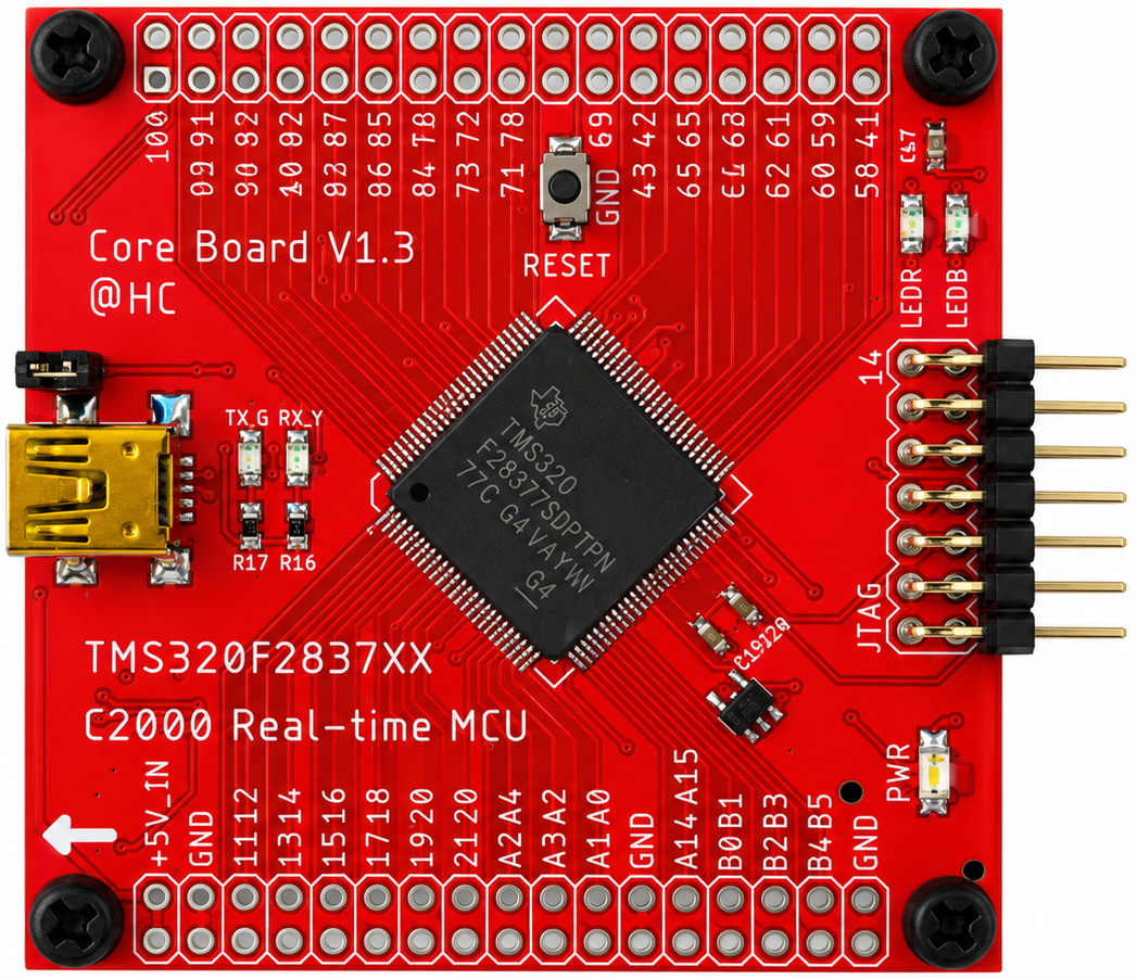 #### TMS320F28377S (LQFP100)
- Dimension: 55 mm x 55 mm
- CPUs: C28x (200 MHz)
- CLAs: Control Law Accelerator (200 MHz)
- Flash: 1023 KB
- RAM: 164 KB
#### Coreboard V1.3 On-Board Hardware Features
- External EEPROM AT24CM02: 1x (I2C-A SDA: GPIO91, I2C-A SCL: GPIO92)
- USB-to-UART: 1x (SCI-A TXD: GPIO84, SCI-A RXD: GPIO85)
- User LEDs: 2x (Red: GPIO41, Blue: GPIO58)
- GPIO Pins: 42x in total
- Analog Pins: 14x in total
#### Coreboard V1.3 GPIO and Peripheral Muxing
- SCI/UART: Up to 3x (SCI-A, SCI-B, SCI-C)
- I2C: Up to 2x (I2C-A, I2C-B)
- CAN: Up to 2x (CAN-A, CAN-B)
- SPI: Up to 3x (SPI-A, SPI-B, SPI-C)
- McBSP: Up to 1x (McBSP-B)
- EQEP: Up to 2x (EQEP1, EQEQ3)
- EPWM: Up to 15x
#### Software Configuration
- Code Composer Studio 12.8.1
- C2000Ware 5.04.00.00
- Compiler TI v22.6.1.LTS
#### TMS320F28377S (LQFP100)
- Dimension: 55 mm x 55 mm
- CPUs: C28x (200 MHz)
- CLAs: Control Law Accelerator (200 MHz)
- Flash: 1023 KB
- RAM: 164 KB
#### Coreboard V1.3 On-Board Hardware Features
- External EEPROM AT24CM02: 1x (I2C-A SDA: GPIO91, I2C-A SCL: GPIO92)
- USB-to-UART: 1x (SCI-A TXD: GPIO84, SCI-A RXD: GPIO85)
- User LEDs: 2x (Red: GPIO41, Blue: GPIO58)
- GPIO Pins: 42x in total
- Analog Pins: 14x in total
#### Coreboard V1.3 GPIO and Peripheral Muxing
- SCI/UART: Up to 3x (SCI-A, SCI-B, SCI-C)
- I2C: Up to 2x (I2C-A, I2C-B)
- CAN: Up to 2x (CAN-A, CAN-B)
- SPI: Up to 3x (SPI-A, SPI-B, SPI-C)
- McBSP: Up to 1x (McBSP-B)
- EQEP: Up to 2x (EQEP1, EQEQ3)
- EPWM: Up to 15x
#### Software Configuration
- Code Composer Studio 12.8.1
- C2000Ware 5.04.00.00
- Compiler TI v22.6.1.LTS
Flashing Firmware with C2Prog
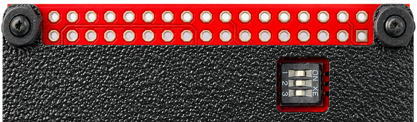
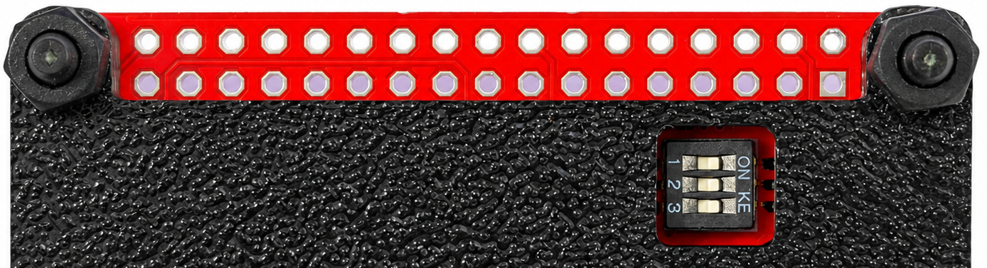
#### Step 1: Configure the Boot Switches
Set the DIP switches as follows:
- Switch 1: **ON**
- Switch 2: **OFF**
- Switch 3: **OFF**
Then connect the board to the PC using the USB port.
 #### Step 2: Program the Firmware
Open **C2Prog** and configure the settings as shown in the image below.
#### Step 2: Program the Firmware
Open **C2Prog** and configure the settings as shown in the image below.
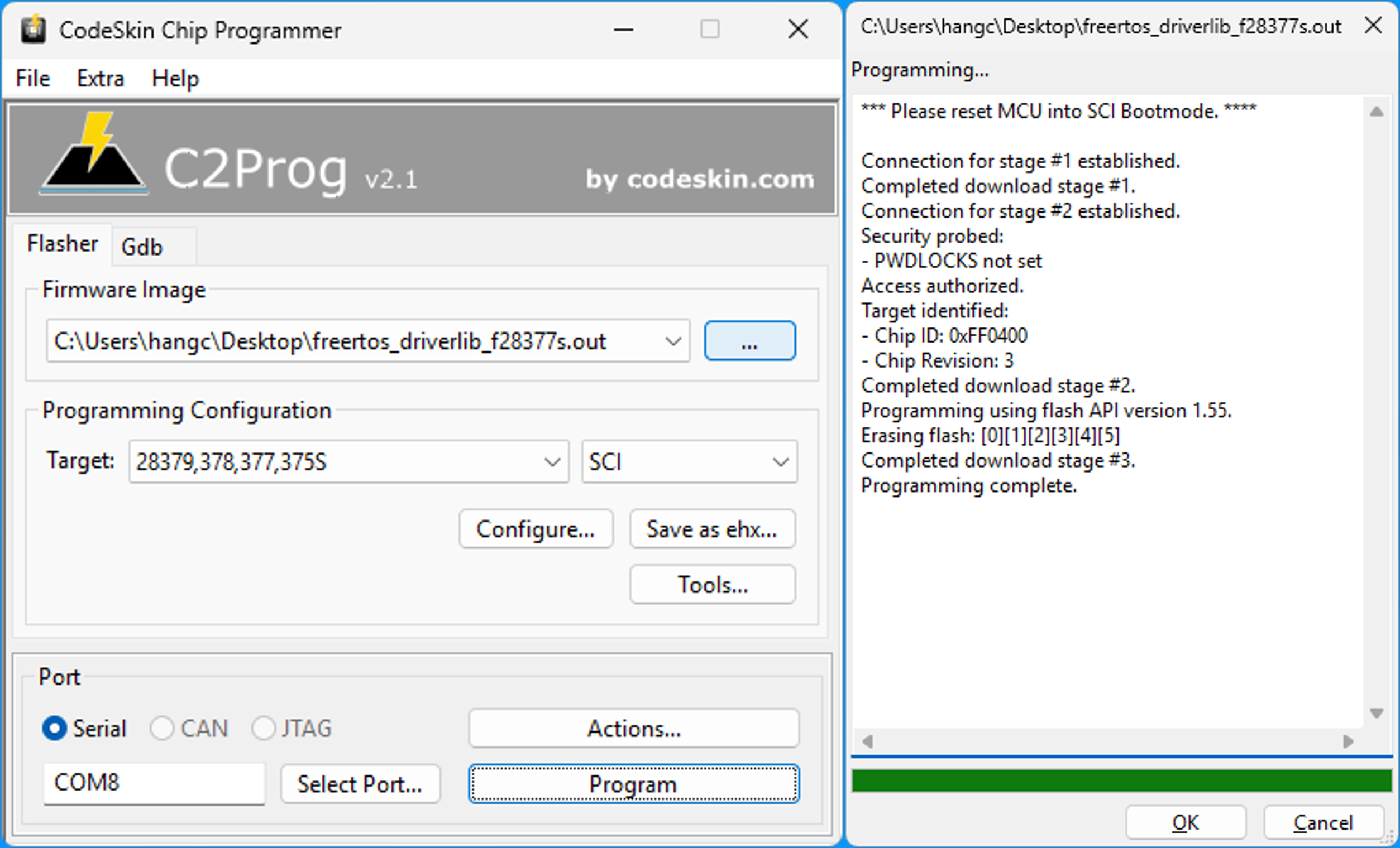 Select the compiled firmware file, then click the **Program** button to start flashing.
#### Step 3: Restore the Boot Switches
After programming is complete:
1. Disconnect the USB cable.
2. Set all DIP switches to the **ON** position:
- Switch 1: **ON**
- Switch 2: **ON**
- Switch 3: **ON**
Select the compiled firmware file, then click the **Program** button to start flashing.
#### Step 3: Restore the Boot Switches
After programming is complete:
1. Disconnect the USB cable.
2. Set all DIP switches to the **ON** position:
- Switch 1: **ON**
- Switch 2: **ON**
- Switch 3: **ON**
 #### Step 4: Reconnect the Board
Reconnect the USB cable to the PC for further testing and verification.
#### Step 4: Reconnect the Board
Reconnect the USB cable to the PC for further testing and verification.
Flashing Firmware with CCS and JTAG
#### Step 1: Open the CCS Workspace
Launch **Code Composer Studio (CCS)** and open the workspace that contains your project.
#### Step 2: Import the CCS Project
From the CCS menu, select:
**Project -> Import CCS Projects**
as shown in the image below.
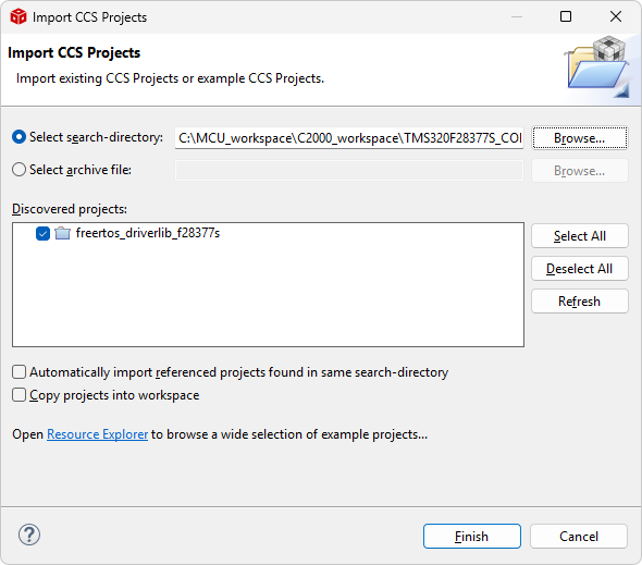 Follow the prompts to select and import the desired CCS project.
#### Step 3: Build and Debug the Project
Build the project to generate the executable file.
Then connect the JTAG debugger to the target board and start a debug session to download and run the firmware.
Follow the prompts to select and import the desired CCS project.
#### Step 3: Build and Debug the Project
Build the project to generate the executable file.
Then connect the JTAG debugger to the target board and start a debug session to download and run the firmware.
#### Demo Project
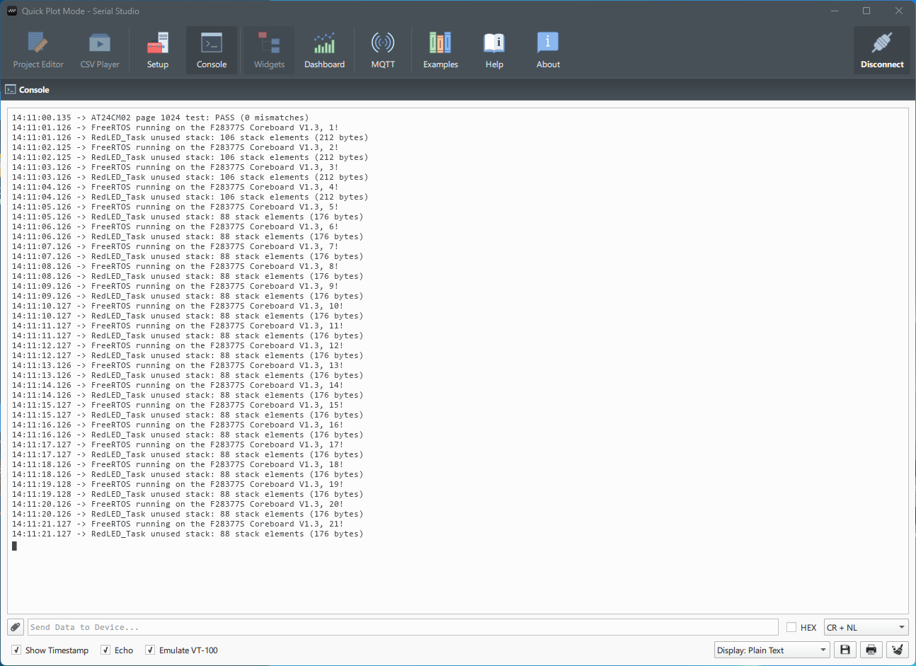
UART: SCIA
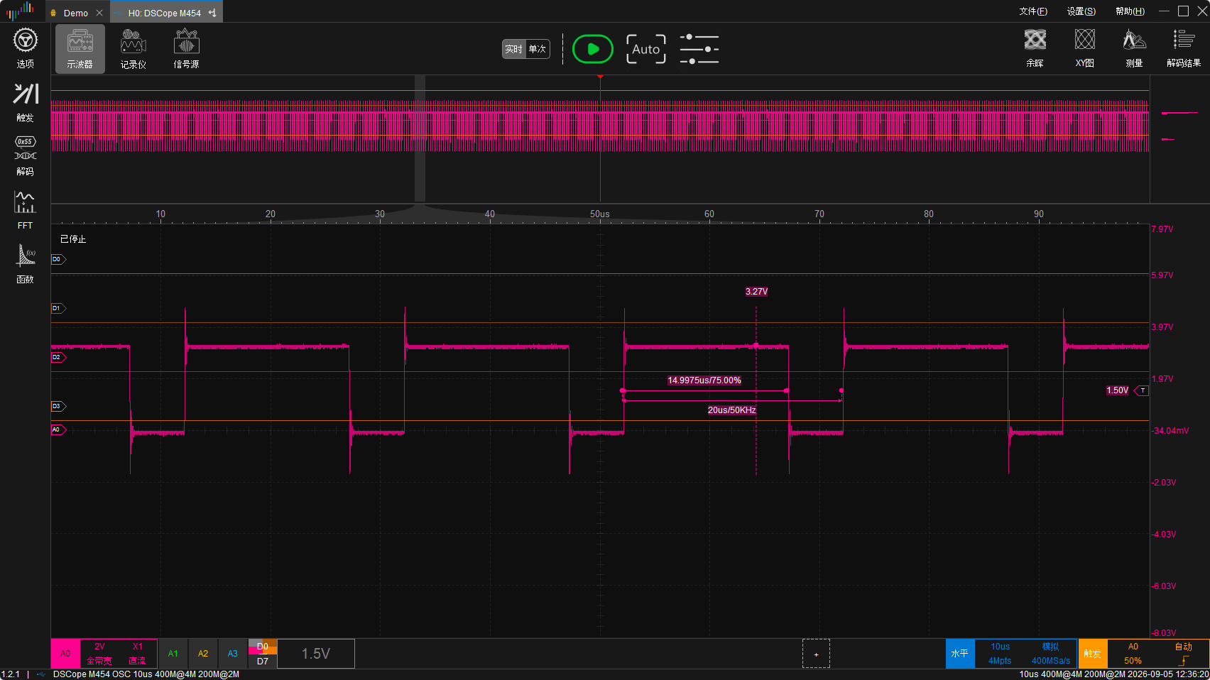
 EPWM6A: 50KHz, 75% Duty Cycle
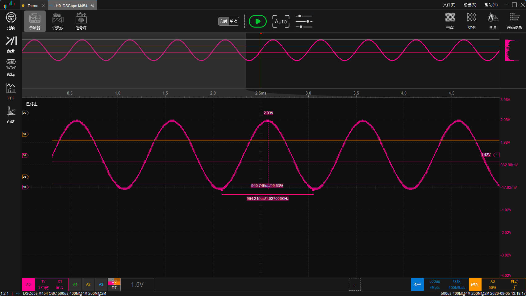
 DACOUTB: 1KHz Sine Wave